There is an ongoing debate on what tolerances are acceptable when aligning your rotating equipment. The debate falls on the “published tolerances” provided by the coupling manufacturers and the tolerances “recommended” by alignment equipment companies, reliability associations and rotating equipment OEM’s. The offset and angularity tolerances are much more permissive from the coupling manufactures than everyone else. Why is that?
Please remember that the published tolerances from the coupling manufactures are related to “The most allowable” tolerance that a particular coupling can accept. There are many other factors that must be considered;
Couplings cannot be aligned at the maximum allowable misalignment for more than one condition (i.e. both excessive angular & offset misalignment occurring at the same time).
Couplings that are misaligned at or beyond their allowable ratings will result in a dramatic drop in coupling life.
Although coupling life cannot be specifically calculated, minimizing coupling misalignment greatly benefits coupling life.
Temperature
Chemical exposure
Run cycle (continuous or start/stop)
All listed above will impact your coupling life, aligning to the listed tolerances below (these are acceptable tolerances, excellent will be half these values) will give you maximum coupling life, not to mention better seal and bearing life as well and all tolerances are SPEED related. The faster the RPM the tighter your maximum allowable shaft alignment tolerance.
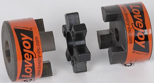
When a coupling is aligned to the proper tolerance it should last its designed life. In a jaw style coupling the insert will show “normal” wear on every other leg if the torque is applied in a single rotational direction and on all legs if the torque is applied in both directions (as in a reversing load). The example below shows normal wear on every other leg that is straight and even (as you would see in a single directional loading application).
(Photo courtesy of LoveJoy, Inc.)
Misalignment will cause uneven wear on the insert legs, as is seen below, and dust may accumulate around the coupling and on the coupling guard.
(Photo courtesy of LoveJoy, Inc.)
In upcoming posts we will show you the normal wear for other types of couplings including grid, gear and disc along with various other failure modes.


