

Centrifugal pumps are common in industry. They are used to move various liquids from one place to another. This work is performed using a rotating pump wheel, or “impeller”, with a number of “vanes” on it. The wheel acts against the pump housing internals, which are either a volute or diffuser style, and produce the force necessary to move the liquid through the pipes to its desired location.
Centrifugal Pump Components
This equipment type includes the following components:
- Motor
- Transmission/coupling
- Pump (Seal, Impeller, Volute)
- Shaft
- Bearings
- Valves
- Piping
Centrifugal Pump Configurations
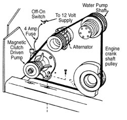
Most centrifugal pump configurations run using an AC non-synchronous motor, a coupling, and a pump setup that has around 2-6 vanes on the rotor. The pump itself consists of a seal, impeller, volute/diffuser, shaft, and bearings. Valves and piping are also components of the pump that need to be considered. Each component introduces its own failure mechanisms, which we will go through below:
AC Non-synchronous Motor
All electrical faults relating to this motor type apply and are a risk for any centrifugal pump setup. This includes cracked or broken rotor bars (especially if the motor starts and stops frequently), bearing fluting (if run on a VFD), as well as any other electrical issue relating to an AC motor.
Bearing faults are also a common failure mode in all motors, proper alignment, lubrication, and keeping the vibration levels below ISO-recommended levels are the key to maximizing the life of your electrical motors. It is recommended they are laser aligned to tolerance, lubricated using ultrasonic lubrication techniques, and using vibration analysis to detect any vibrational anomalies like unbalance or structural resonance.
Coupling/Transmission
The coupling/transmission is another crucial component in centrifugal pumps. A coupling is the most common on pumps in industry, so we will put more focus on equipment that relies on a coupling for transmitting the rotational energy from the motor to the pump.
There are several different types of couplings in industry, such as:
- Disc Pack
- Flexible Gear
- Grid
- Bellows
- Elastomeric
They all have their benefits and drawbacks. Load capabilities, misalignment tolerances, and ongoing maintenance are some of the main factors considered when determining the right coupling for the right application.
A visual inspection of the coupling, using a strobe light, can make it easy to find wear or damage on many of the couplings that are used in the field. When performing a laser alignment on couplings it is a good idea to align to the standard tolerance rather than the “advertised” tolerance in the coupling installation guide. Just because the coupling can handle the misalignment, doesn’t mean that the bearings and seals can. Some couplings need to be lubricated or have other ongoing maintenance requirements that we need to be aware of. Please review the installation/maintenance guide that came with it from the OEM.
We also see belt-driven pumps that are at risk for belt wear, misalignment, and over-tensioning. By using a laser alignment tool and tensioning your belts properly, you will experience longer belt life and less wear to the sheaves, bearings, and seals.
Pump Components
The pump includes the shaft, bearings, impeller, and pump housing. The bearing arrangement is going to depend on the pump style, load, and transmission type. It is common for pumps to have one roller bearing on the couple side of the pump and two angular contact bearings back-to-back in order to handle the axial load.
Pump wear, cavitation, and bearing wear are the most common failure modes for the “pump” component on this machine type. Proper lubrication is the key to achieving long bearing life; most pumps have a sight glass that can be used to visually inspect lubricant levels. It is important to keep the sight glass clean, as they tend to “stain” right at the level it is at the most, which can be misleading if it gets low.
Vibration analysis can detect most of the previously mentioned faults. Keep in mind that vane pass frequencies are at (Number Vanes X RPM). A high 1x vane pass vibration indicates a high load on the pump. It is also recommended to take a vibration reading that is from 0-120KCPM and watch for a raised noise floor in the acceleration spectrum that would indicate cavitation. If you suspect cavitation, you can manipulate the valves while viewing live data and see it change. Take a vibration reading in all three directions on both bearing locations. Using enveloping techniques in data collection will help with early detection.
Centrifugal Pumps and Piping
Piping can have an effect on the overall life of your centrifugal pumps. This is why it is important to calculate the “head pressure” if you were to imagine having no output piping at the top of the pump and simply allowed the liquid to shoot out of the top. The height that the liquid would reach is the pump head. This can be calculated as a function of HP, pump rotor diameter, and speed. Having proper head pressure is a necessity if you want your pump to run efficiently and reliably. The height and number/angle of bends in the piping have an affect on pump head and need to be kept in mind for proper operation. It is also a good idea to stagger your pipe hangers at varying spacing in order to keep from entering into a resonance.
Valves
Valving restricts or cuts off flow entirely either to or from the pump. If you don’t operate your valves properly you can pretty quickly and severely damage your pump. Valves are also a component to be considered when looking at maintenance or problems that can occur in pumps running in an industrial environment. Improper valve control can cause considerable damage to a pump in a short amount of time.
Running Centrifugal Pumps
Another important factor in this style of pump is related to running them. It is pretty common for industrial facilities to have redundancy in their pumping systems, this is where there would be a “primary” and a “secondary” unit running either one or the other at a time. These types of pumps like to run, if they are left stationary for long periods of time you will experience issues that wouldn’t be there if the unit was in continuous operation. It is very important that these pumps are both used on a scheduled basis and monitored using vibration analysis. If not, your backup could be damaged without anybody knowing about it, removing the biggest benefit from having that redundancy to begin with.
There are many more types of pumps and configurations out there in the industrial world, but these are very common and you now have a better understanding of the operation, troubleshooting, and maintenance of centrifugal pumps.


1 Comment
Thank you for the information you share. This is very exciting and educational