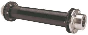
The majority of precision shaft alignments are relatively close coupled where there are only a couple of inches between the shaft ends of the driver and driven elements. Close coupled alignment quality is traditionally displayed as angle (driver to driven) and offset (at the center of the coupling).
The question is what do you do when you have a spacer shaft? The answer is, it depends on what tool you are using and if it has a spacer shaft function. One thing to understand is the modern laser alignment tool is measuring the same regardless of the span. In other words, the alignment condition is the same, how you correct for misalignment is the same (adjust the driver until you meet tolerance) but how you might want to display the alignment (or misalignment) quality can change. It can be displayed as either angle/angle (at A and B below) or as angle and offset at mid-span of the spacer.
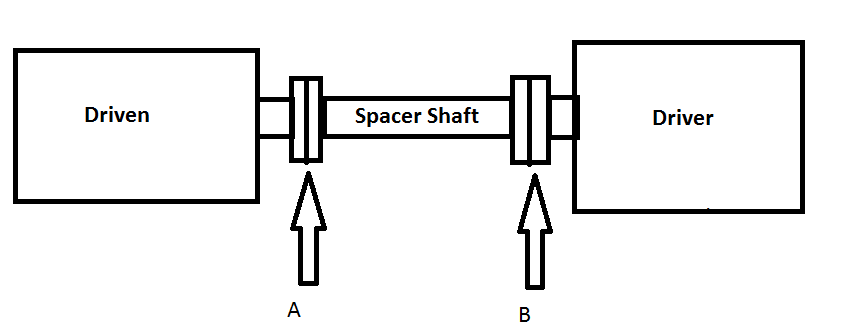
First some definitions.
Angle A (mils/inch) – Angle of the Driven element to the spacer shaft
Angle B (mils/inch) – Angle of the Driver to the spacer shaft.
Angle C (mils/inch) – Angle of the Driver to the Driven. Traditional angularity in close coupled alignments.
Angle C (mils/inch) = Angle A + Angle B so if you control angle C you are also controlling angles A and B
Offset – In mils at a specific point (designated by the user) on the coupling. Traditionally at the coupling center.
Remember 1.0 mil = 1 thousandth = .001 inches
Here is an example:
Take a 1200 RPM cooling tower with a 100” spacer shaft. A traditional close coupled tolerance for 1200 RPM, would be 1.0 mil/inch maximum allowable angle with an offset of 6 mils at the center of the coupling. On a spacer, however the offset from the driver to the driven can change by 100 mils. This is calculated by multiplying the 1.0 mil/inch angle x 100” length = 100 mils. If you use traditional close coupled tolerances and measure the offset mid-span you will likely work much harder than needed. A recommendation would be to adjust for an allowable mid-span offset to be +/- 50 mils. (50 inches mid-span x 1.0 mils/inch) This along with an angle of 1.0 mils/inch or less would lead to an excellent alignment.
An easy to remember rule of thumb would be to adjust the offset tolerance (regardless of speed) by 0.5 mils/inch x ½ the span. In our example, the offset tolerance would then be (0.5 mils/inch) x 50 inches = 25 mils. If this spacer was aligned to 1.0 mils/inch angle and 25 mils offset mid-span it would be easily achievable, tighter than angle/angle and an excellent alignment.
Here is an alignment with a 100” spacer displayed as an angle at each flex plane (angle/angle) in Fig 1. and then as angle/offset in Fig. 2 with the offset at 50” or mid-span. Notice that in both cases the feet values are the same. The machine positions and therefore the alignment condition are the same. The difference is simply in how the results are displayed.
Fig. 1 – Angle/Angle (Angle at each flex point) Fig. 2 – Angle/Offset (Offset mid-span)
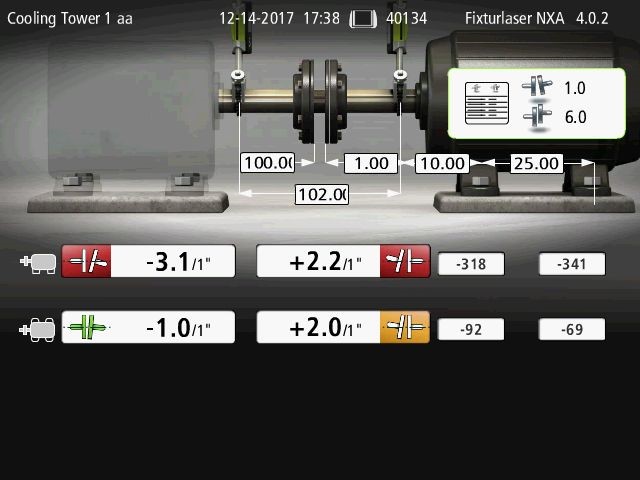
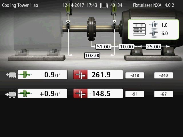
Fig. 3 shows an excellent alignment with everything in tolerance (all green) when displayed as angle/angle. Fig. 4 is the same alignment but displayed as angle/offset. It only appears out of tolerance because the offset tolerance value (outlined in red) was not adjusted for the span. These are in fact the same alignment quality.
Fig. 3 – Aligned angle/angle Fig. 4 – Aligned, angle/offset
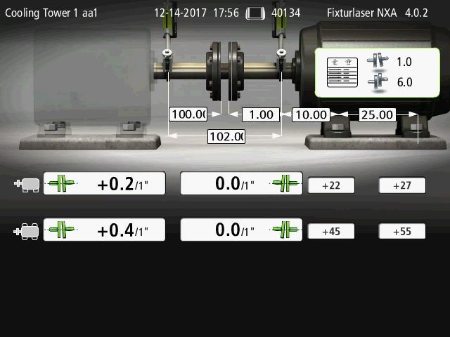
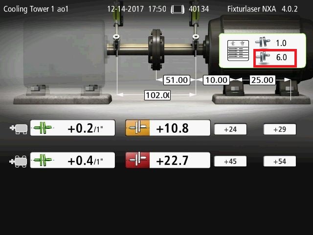
Fig. 5 Is the same alignment as Fig. 4 above however the offset tolerance value has been adjusted to 50 mils (for this example) per the “Rule of Thumb” used above.
Fig. 5 – Angle/Offset with offset tolerance adjusted for span
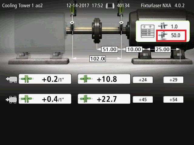
The misaligned condition is the same for Figs. 1 and 2. The aligned condition is the same for Figs. 3, 4, and 5. If you look at the feet values you can see the machines are positioned the same relative to each other. What has changed is the how the results are displayed and the offset tolerance being accepted based on the spacer length.
As a spacer shaft is generally expected to be able to handle more misalignment, the longer the spacer, the offset tolerance can be “loosened” as compared to a close coupled machine. One way to do that is to use a spacer shaft program and display the alignment results as angle/angle. The tolerances are typically looser so the alignment can be done much quicker. This is shown in figure 3 which shows an excellent final alignment using the angle/angle method.
Another method is to use angle/offset but adjust the offset for the span. Figs. 4 and 5 are also excellent alignments. They are in fact the same alignment as shown in Fig. 3. All three results show an aligned machine. If you just pay attention to the red and the orange coupling icons and not the numbers you will continue to work unnecessarily even though the machine is aligned. If you adjust the offset tolerance for the span you will also be done quickly and efficiently and show that all coupling values are in tolerance.
Conclusions:
1 – Spacer shafts can be effectively aligned with either spacer shaft (angle/angle) or close coupled (angle/offset) methods.
2 – Spacer shaft tolerances are typically more forgiving than close coupled tolerances.
3 – When aligning a spacer shaft using angle and offset adjust the allowable mid-span offset based on the angularity tolerance. (Angularity mils/inch x ½ spacer length)
4 – Alternatively an easy to remember rule of thumb is .5 mils/inch x ½ spacer length for a mid-span offset. Will be a little tighter tolerance but easy to remember and typically easily achievable.
5 – If you use a tolerance based on span the alignment will also be done quickly and efficiently.
6 – Regardless of method it is important to understand the numbers (coupling values) and not just rely on red/orange/green color guidance.
Additional Resources
Video showing a spacer shaft alignment using the Fixturlaser NXA Pro’s spacer shaft program
https://www.youtube.com/watch?v=ub1Y5ResxsU&t=49s
Other considerations for spacer shafts.
https://acoem.us/shaft-alignment/spacer-shafts-jack-shafts-line-shafts-spool-pieces/
https://acoem.us/shaft-alignment/cooling_tower_rough_in/
https://acoem.us/shaft-alignment/cooling-tower-adventures/
https://acoem.us/shaft-alignment/align-cooling-tower-hour/
Article from Lovejoy that discusses spacer shafts.
http://www.couplinganswers.com/2015/08/what-is-difference-between-spacer-vs.html


