Vibration data was taken on a motor/pump during initial training on the Acoem Falcon. This pump was chosen based on history and a visual inspection. The visual inspection pointed towards…
Read MoreA Pump Tale: Misalignment Exposed

Vibration data was taken on a motor/pump during initial training on the Acoem Falcon. This pump was chosen based on history and a visual inspection. The visual inspection pointed towards…
Read More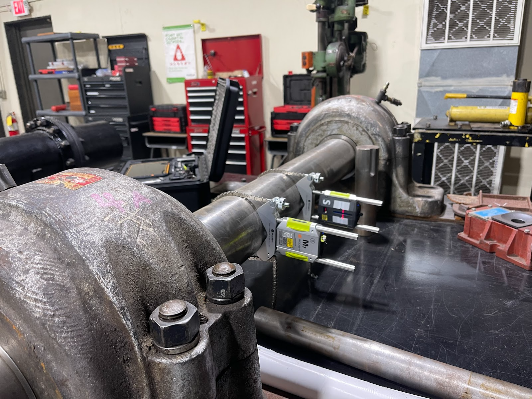
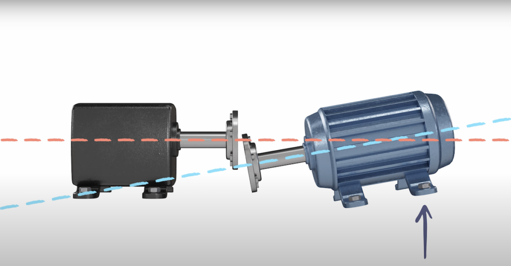
Acoem alignment systems allow the user to input thermal growth (offline to running) targets prior to performing a precision shaft alignment. Using targets allows the alignment to be completed to…
Read More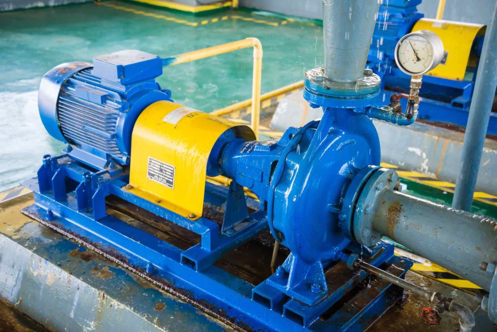
Recently I came across a new pump skid where an alignment check was performed after installation during new construction. Even though it did not have much run time there were…
Read More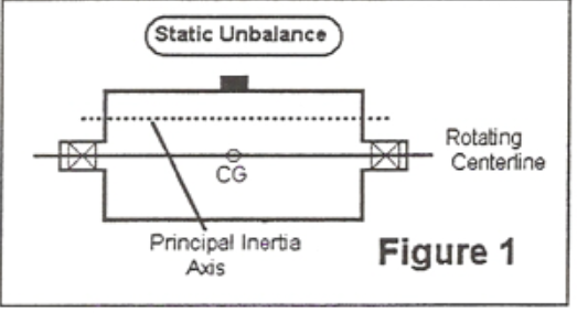
According to the International Organization for Standardization (ISO), unbalance is “that condition which exists in a rotor when the vibratory force or motion is imparted to bearings as a result…
Read MoreKnowing the correct rotational speed is critical when performing machinery diagnostics. A strobe light can be an excellent tool for determining speed. Look for a unique mark such as a…
Read MoreAlthough most machines are aligned with the coupling installed there are occasions where it is better to align a machine uncoupled. A couple of considerations: 1 – Shafts are rotated…
Read More
We often get asked why we don’t input a coupling diameter when performing a precision shaft alignment with the ACOEM laser alignment systems. The coupling diameter (or more correctly sweep…
Read More
A lift check isn’t always done when performing a precision shaft alignment, nonetheless excessive lift can be the cause of alignment frustration. Here is a recent example from…
Read More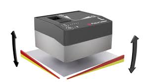
The Fixturlaser level is calibrated to earth level out of the box. If the level is used without a fixture it reads level directly. If a fixture is used, however,…
Read More
The Fixturlaser Level is a high precision two axis digital machinist level. The primary application is base leveling. The Fixturlaser Level offers the following advantages: Two axis live measurement Calibrated…
Read More
The validity rule is an important concept in precision shaft alignment. It can be used to confirm that your readings are accurate and is why we don’t have to rotate…
Read More
Unbalance (Imbalance) is often defined as the unequal distribution of the weight of a rotor about its rotating centerline. A rotor can be balanced either in-place or in a balancing…
Read More
The goal of a precision alignment is to align the machine within tolerance when at operating condition. Many, but not all, machines are aligned without the need to compensate for…
Read More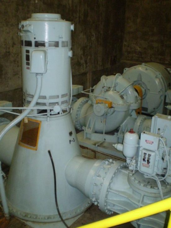
Many modern laser alignment systems include inclinometers that aid in the alignment process. Inclinometers, however, don’t work on vertically oriented machines. These include vertical “C” faced machines as well as…
Read More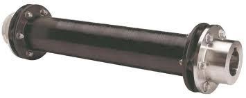
The majority of precision shaft alignments are relatively close coupled where there are only a couple of inches between the shaft ends of the driver and driven elements. Close coupled…
Read More