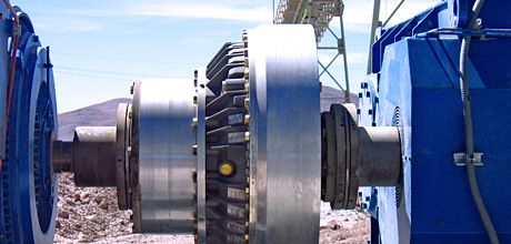
I recently took a call from a customer at a coal-fired power plant in Arkansas. He was performing a precision laser shaft alignment of a 450 HP, 1750 RPM electric motor coupled by a fluid drive coupling to a gearbox on a coal conveyor. Similar to the one pictured above.
This conveyor is one of two side by side conveyors each is 60” wide by 500 yards long. The gearbox has a backstop which only allows a clockwise rotation as viewed from the rear of the electric motor. The other conveyor was in operation during the alignment.
Mike was using a Fixturlaser NXA Pro, with 12” extensions rods which were needed to get the sensors high enough to shoot the lasers past the OD of the coupling.
He was having repeatability issues and said he could feel vibration at the ends of the extension rods. Also, this style of fluid drive is typically treated as an uncoupled alignment and Mike wanted to verify the best way to take the measurements. Shaft Alignment with a Fluid Coupling.
We discussed running the built-in repeatability test of the NXA which tests the vibration levels of the surrounding environment and allows the user to adjust the measuring sampling time accordingly. Also turning on the screen filter.
As the gearbox shaft could only rotate one direction and the fluid drive coupling allows the motor shaft to turn independently of it, I recommended using the Tripoint measuring method and simply matching the inclinometer values of the S and M Sensors at each measuring position.
By using Tripoint and taking the 1st set of measurements at 9, 12 and 3 o’clock, performing a Verti-Zontal Compound Move as needed then re-measure at 3, 6 and 9 o’clock the “shaft turning” required will be minimal.
When he finished Mike emailed me the following.
“Initial Repeatability test @ 3 seconds setting: S Sensor value changed by 20 mils (.020″) due to vibration.
Final Repeatability test @ 10 seconds setting to compensate for vibration: S Sensor value changed by 1.1 mils (.0011″) M Sensor value changed by 0.7 mils (.0007″).
Dimensions: S to M sensor 28.875”, Coupling center to M sensor 6.750”, M sensor to front motor foot 15.00”, Front motor foot to rear motor foot 28.750”.
Here are the results in 2 moves:
Vertical Angle; -0.1mil/1″, Vertical Offset; +0.8 mil. Horizontal Angle; 0.0 mil/1″, Horizontal Offset -0.4mil”
Editor’s note: At 1800 RPM max. allowable angle is +/- 0.7mil/1″ and max. allowable offset is +/- 4.0 mil.
Even with high vibration levels in the area this shaft alignment was easily corrected after compensating for the vibration. Its always a good practice to run a repeability test at the beginning of the alignment as it only takes a few minutes to do so, which ultimately can save you hours and a lot of frustration during the alignment!


4 Comments
Excellent information.
its really excellent information, but I have a question..
what the right procedure to replace the gearbox backstop filter..?
thanks
Thanks for your comment. I would contact the gearbox manufacture for their recommended procedure.
Thanks for this great information, i got a question about alignment dimensions.
As you know alignment machines request transducer to coupling center distance. If it is possible i am removing fluid coupling first and then doing alignment. In that case half of the distance between the gearbox shaft and motor shaft is my coupling center, i hope thats right? I am using spacer shaft tolerance limits here.
If i can not remove fluid coupling i am attaching one sensor to the delay chamber of fluid coupling and trying to turn both motor shaft and gearbox shaft at the same time with help of some tools. Am i going to use same distance for coupling centers in this case?