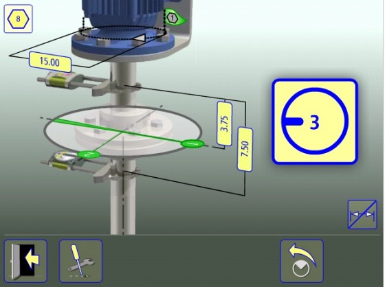
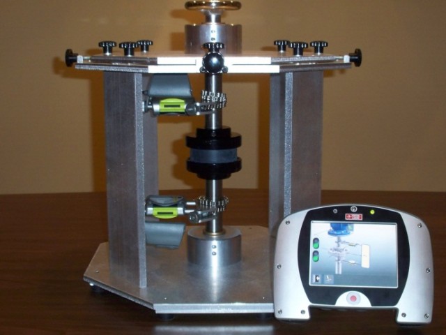
The inclinometers in a laser alignment system work against gravity in the horizontal plane for a typical horizontal shaft alignment. When performing a vertical shaft alignment, the process will be different. Here is the process for aligning a vertically-mounted C-faced motor as shown on a vertical alignment demonstrator:

Photo of Vertical Shaft Alignment Training Demonstrator courtesy of V-Tek Associates. www.vtekassociates.com
-
- Mount the sensors across the coupling. Special considerations might need to be made for rigid couplings or with space considerations. (http://acoem.us/blog/2011/09/15/vertical-pumps-alignment/)
- Input dimensions per the prompts. Special dimensions typically include diameter of the bolt pattern and number of bolts.
- Enter the number the bolts. Typically start the number one bolt at a place you can make an adjustment.
- Measure starting at bolt 1. Three measurements are taken 90 degrees apart starting at bolt one.


- Correct the offset by positioning the laser at a point and adjust live until within tolerance.
- Rotate the laser 90 degrees and adjust the other offset live.
- Remeasure to check results.

 Have you done any vertical alignments lately? Leave a comment! We’d love to hear about it. Also don’t forget to sign up for our Realign America campaign. There are prizes!


1 Comments
good works its very useful for us thank you very much