Gas engines and reciprocating compressors, used in the gas compression industry, have a certain amount of crankshaft end play or thrust (as it’s commonly called). The amount of thrust is determined by the OEMs of the machines. The crankshafts of these machines must be able to “float” axially to prevent excessive/premature bearing wear.
When new compressor skids are fabricated, engines “swung” or compressor crankshafts or bearings replaced during maintenance the thrust must be set (as well as the proper axial spacing of the coupling hubs). Having the thrust set incorrectly will also affect the quality of the shaft alignment results whether using dial indicators or a laser alignment tool.
Note: if the driver is an electric motor instead of an engine then the magnetic center of the motor rotor should be set as well as the compressor thrust, per OEM specifications.
Most compressor skids use a shim or disc pack coupling. Shim pack couplings can handle a lot of torque and require no lubrication.
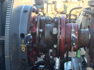
They are also very rigid, and the shim packs do not wear well with misalignment which causes cyclical flexing of the shim packs resulting in premature failure.
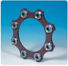
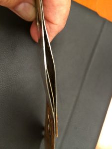
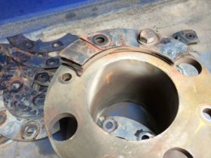
Due to the “rigidness” of the shim packs if the thrust is not set correctly, with the crankshafts having no end play, the coupling will influence the rotational centerline of each machine due to the large bearing clearances between the bearing Babbitt and crankshaft journals.
During a recent precision shaft alignment of Cat 3516 engine and Ariel JGE-4 compressor (the engine had been replaced) the thrust was checked and in tolerance. The initial alignment readings showed a vertical angle of +1.1mils/1” with the vertical offset being close and the horizontal position was in tolerance. The front of the engine needed to be lowered 176 mils (0.176”) and the rear needed to come down 45 mils (0.045”).
After removing the shims, checking the horizontal alignment, and tightening the hold bolts a fresh set of alignment measurements were taken. The results were not close. A 2nd set of alignment measurements were taken to confirm the previous results and did not repeat to the previous set.
A check of the thrust revealed there was none. Zero, no crankshaft end play. A closer look at one of the coupling shim packs confirmed the components were in a bind as a shim pack had a wave or twist in it.
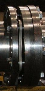
With the front of the of the engine 176 mils high the thrust was set with the coupling hubs open at the bottom due to the vertical angularity. Lowering the front of the engine closed the gap between the coupling hubs eliminating the thrust. The mechanics readjusted the thrust with the axial jack bolts on the engine moving it forward. After tightening the hold down bolts the coupling shim packs were “relaxed” with no twist and the alignment measurements repeated.
One slight shim change vertically and slight horizontal adjustment and done. Final results showed the vertical angle now at 0.3mils/1” and vertical offset of 3.0 mils. The horizontal position was in tolerance as well. The tolerances we used for this alignment were an angular misalignment of +/- 0.7mils/1” or better and offset misalignment of +/- 4.0 mils or better.
Thrust should be checked through out the alignment process as nothing should be taken for granted (or assumed) when preforming a precision shaft alignment.


