Most maintenance personnel understand that documenting a precision shaft alignment is a good idea, but don’t always understand how to interpret the data. Here is a quick primer on how to read a typical alignment report. This shaft alignment report happens to be from a Fixturlaser NXA Professional but all alignment reports should contain similar information in an easy to understand format.
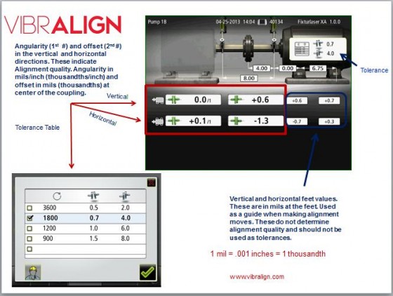
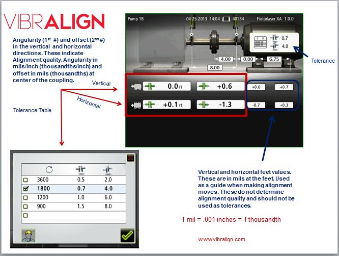
As a refresher, the alignment condition of two machines is defined by the angularity in mils/1″ and the offset in mils at the coupling in both the vertical and horizontal planes. Remember in imperial units:
1.0 mil = .001” and 0.1 mil = .0001”
The alignment condition for two machines is not defined by the foot values but rather the angularity and offset values at the coupling.

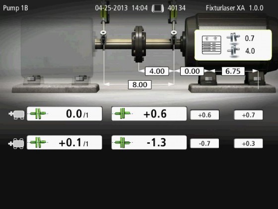
In the above example, the green coupling icons give the reader a quick indication that everything is below the maximum allowable alignment tolerances.
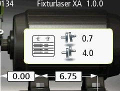
Looking at the closeup photo below, the actual tolerances selected for this alignment, where you want the alignment to be at or below, are shown in the middle of the motor. In this case 0.7 mils/1” of angularity and 4 mils offset.These tolerances happen to be the suggested precision alignment tolerances for an 1800 RPM machine.

Looking at the alignment information below the picture of the stationary and movable machines; the top line of numbers (to the right the machine icon with two feet) represents the angularity, offset, front foot and rear foot values in the vertical plane. All values are in mils except for the angularity which is in mils/1”.
Vertical: Angularity Offset Front foot offset Rear foot offset

The bottom line of numbers (to the right of the machine icon with four feet) represents the angularity, offset, front foot and rear foot values in the horizontal plane.
Horizontal: Angularity Offset Front foot offset Rear foot offset

Bottom line, look at the angularity and offset in both the horizontal and vertical planes to quickly determine how good the alignment is.
Put it all Together:

Other resources relating to this post:
To read about angularity check out this blog post:
https://acoem.us/blog/2012/11/27/defining-angularity-shaft-alignment/
For an excellent discussion on tolerances as it relates to feet values, check out:
https://acoem.us/blog/2012/05/04/foot-tolerances-vs-coupling-center-tolerances-for-shaft-alignment/


3 Comments
Great post, Mike. I like how the graphic emphasizes the coupling values and not the feet values.
Expressing angularity ‘per inch’ is definitely the way to go. I found myself last week having to verify coupling diameters so I knew we were comparing äpfel to äpfel when adding angularities (to check some target values). I think I have the guys convinced to always put ‘1.0 inches’ in so there’s no second guessing later.
Very informative. Thank you.
This post is a very good guide. Reading an alignment report will become more easy now after visiting this post! Every idea is direct to the point. Perfectly laid out.