

Balancing a rotating machine is not complete until the final result is compared against a defined and appropriate acceptance tolerance. Tolerance gives the technician a measurable stopping point and helps determine whether the remaining imbalance or vibration is acceptable for the machine and its operating conditions.
The Acoem Wireless Balancer offers either ISO 21940 or ISO 20816-3 as balancing tolerances. Inputs will be slightly different depending on the selected tolerance. You can also balance without selecting a tolerance.
Choosing between the two standards depends largely on what information is available. ISO 21940 uses rotor-specific information to calculate permissible residual imbalance, while ISO 20816-3 evaluates the machine using vibration velocity measured under installed operating conditions. Understanding how each option works will help you select the most practical tolerance for the balance job.
ISO 21940 Balance Tolerance Standards
ISO 21940 is commonly selected when the rotor weight and correction radius are known. This makes it well suited for applications where accurate rotor information is available before the machine is returned to service. This would typically be on a balance stand.
ISO 21940: Balance Tolerance to a G standard. Specifies permissible unbalance based on machine type and operating speed.
According to one of my early mentors, D.L. “Pete” Bernhard with IRD Mechanalysis in IRD Technical Paper 14, the “G” number is the product of a specific unbalance, e, and w, the rotor maximum angular velocity in radians (G = e x w = constant). It is a constant for rotors of the same type. Inputs on the Wireless Balancer include:
- The Machine Type
- ISO Grade Level
- Rotor Weight
- and Correction Radius
This can be selected when used on a balance stand where rotor weight is accurately known. This standard replaced the well-known ISO 1940-1.
Practical Meaning: A G 6.3 rating means the rotor’s center of gravity is permitted to move at a maximum vibration velocity of 6.3\mm/s ( .248 ips) at its maximum operating speed.
The following screens show where the ISO 21940 tolerance is selected and where the machine type, grade level, rotor weight, and correction radius are entered within the Wireless Balancer.
Selection 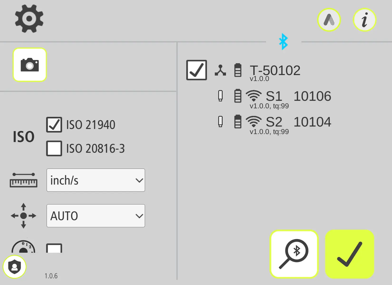 | Machine Type  |
ISO Grade Level 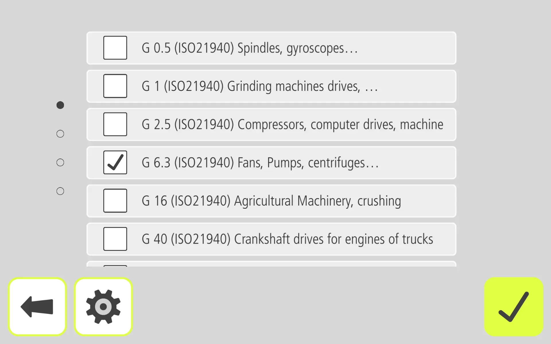 | Rotor Weight 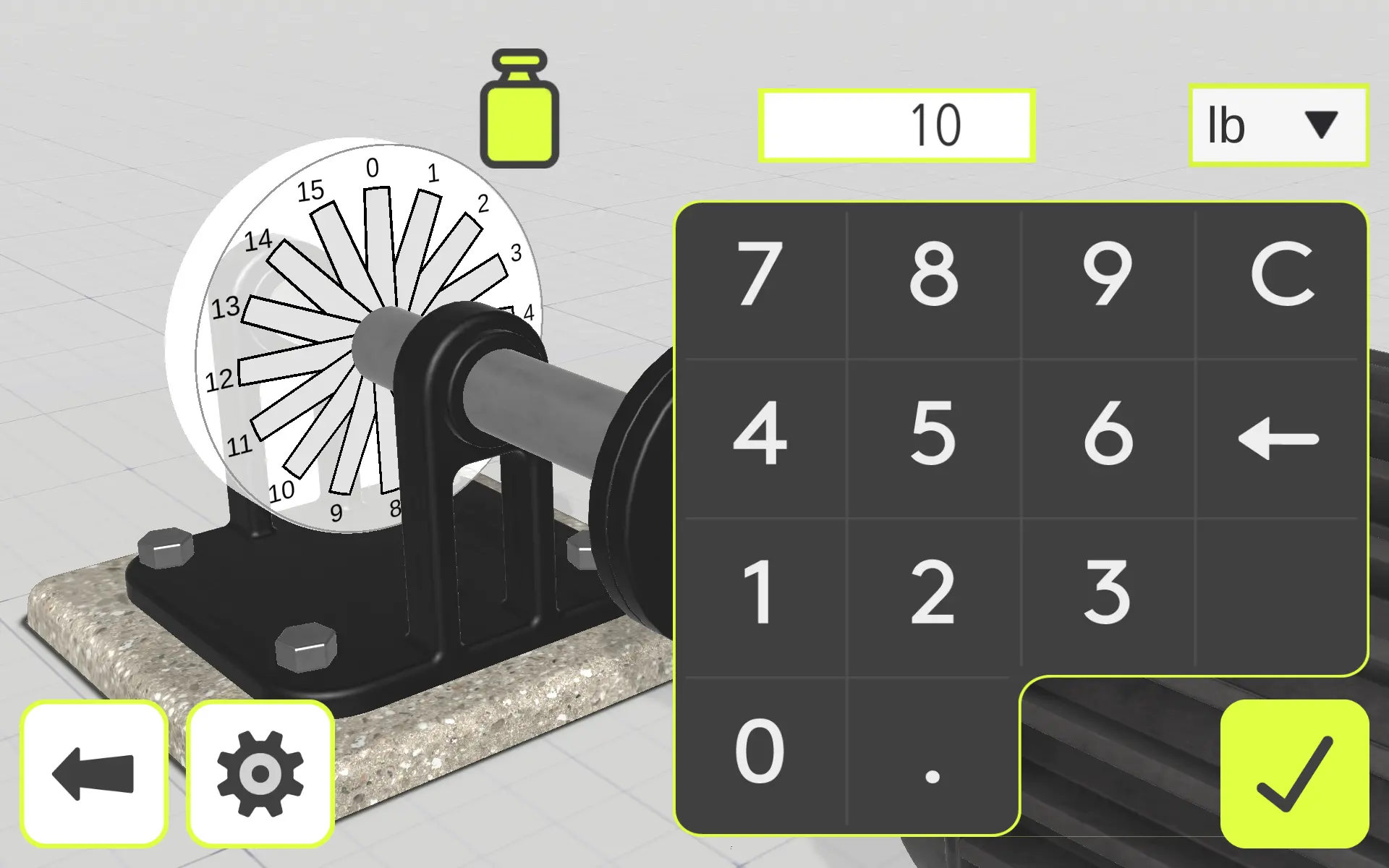 |
Correction Radius 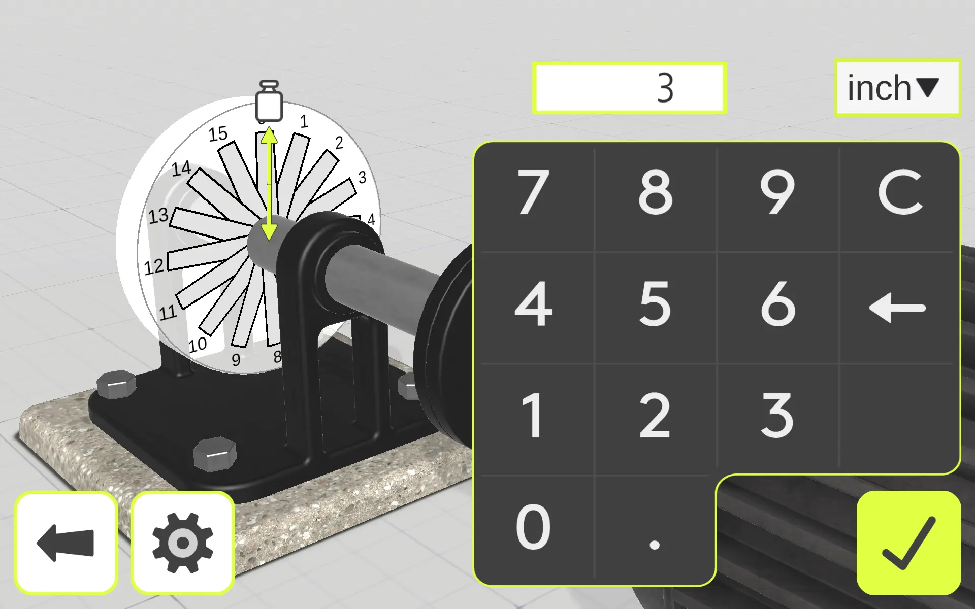 | Balanced Below G 6.3 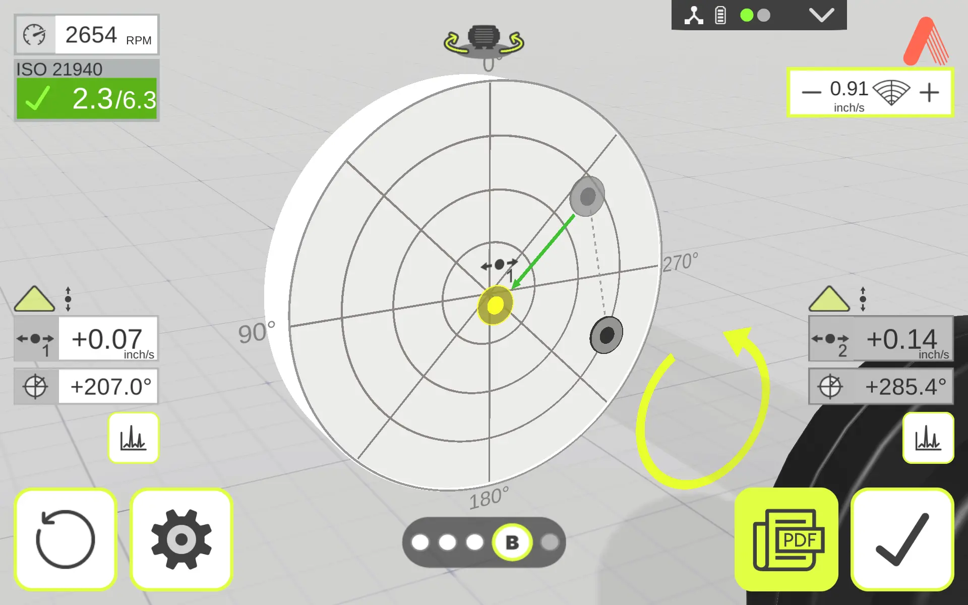 |
ISO 20816-3 Balance Tolerance Standards
ISO 20816-3 provides a practical alternative when the rotor’s weight is not available. Instead of calculating an allowable residual imbalance, this method evaluates the machine using the vibration velocity measured while it is installed and operating. This is normally used in field balancing.
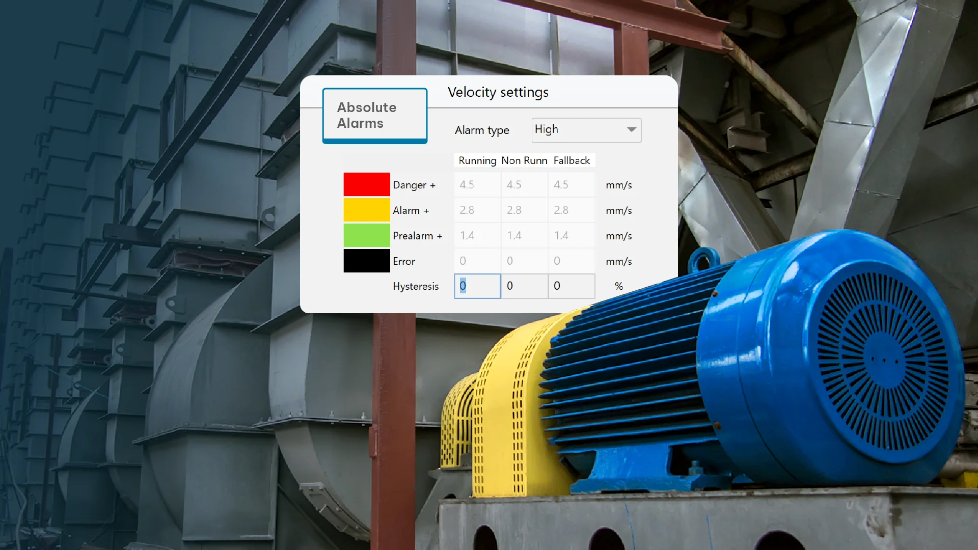
ISO 20816-3 – Balance tolerance based on vibration velocity.
Primarily used in Field Balancing since the weight of the rotor is usually unknown and vibration velocity is used after installation to verify overall operational health of the machine. This standard replaced and combined two older standards ISO 10816-3 and ISO 7979-3.
Inputs on the Wireless Balancer include:
- The Machine Type
- Foundation Type
- and Machine Speed
These inputs allow the application to select the appropriate vibration evaluation criteria for the machine. Once the correction weights have been installed, the final vibration velocity can be compared against the applicable tolerance to determine whether the machine has reached an acceptable operating condition.
Practical Meaning: ISO 20816-3 helps answer whether the machine’s remaining vibration is acceptable after balancing. Because the standard evaluates overall vibration velocity, technicians should remember that vibration from misalignment, looseness, resonance, bearing defects, or other mechanical conditions can also affect the final reading.
The following screens show the ISO 20816-3 selection process and the additional machine information required by the Wireless Balancer application.
Tolerance Selection  | Machine Type 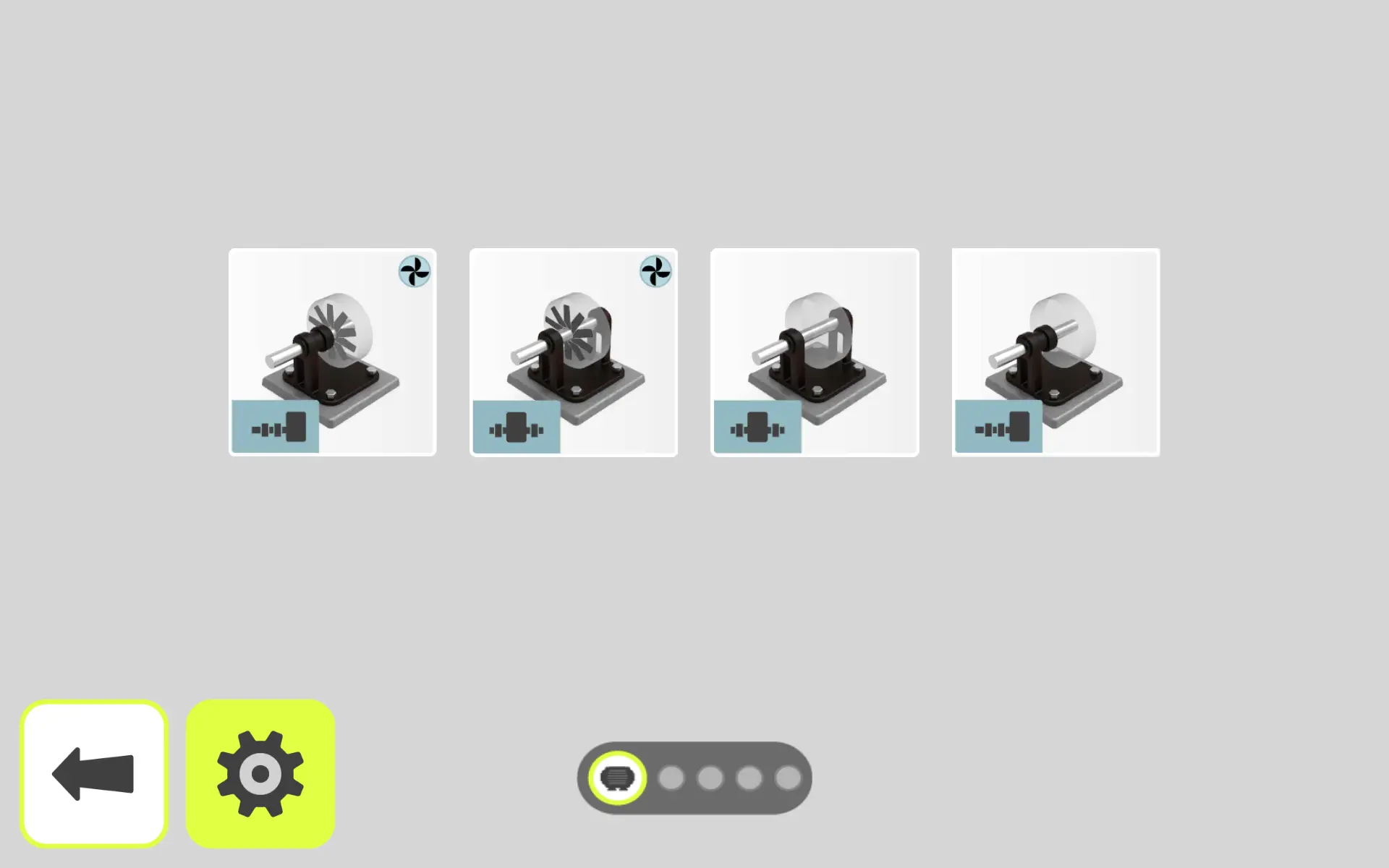 |
Rigid or Flexible Mount 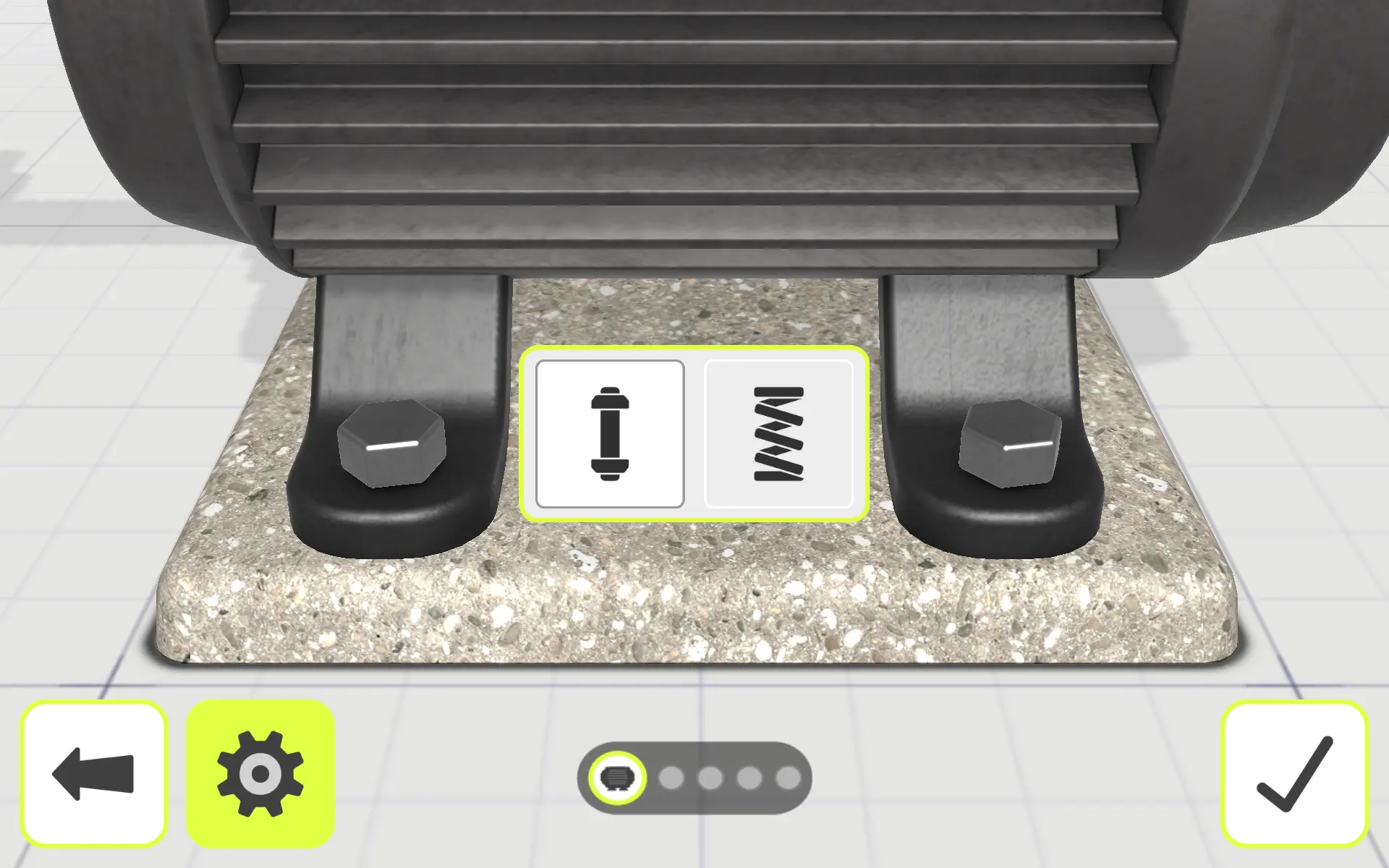 | Horsepower Above or Below 400 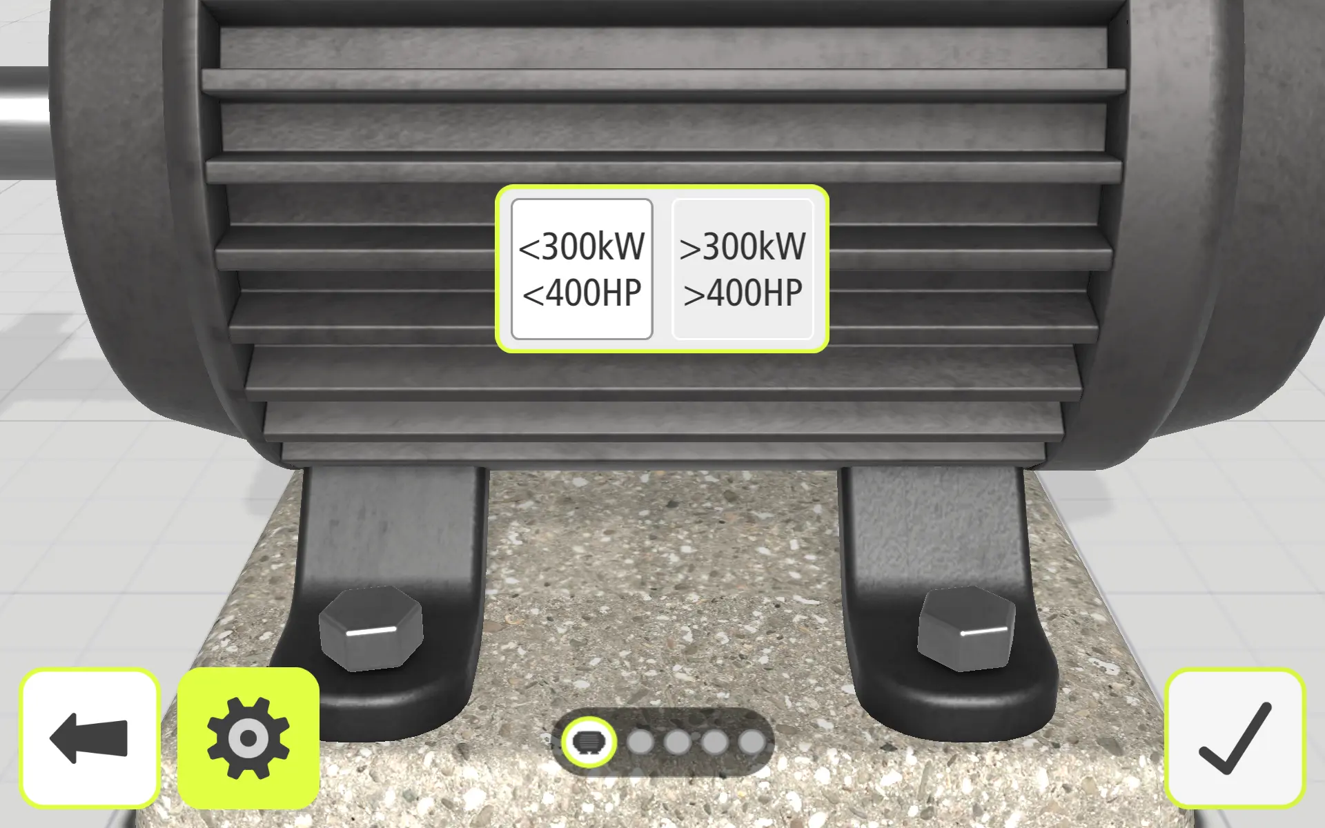 |
Aligned Below ISO Tolerance 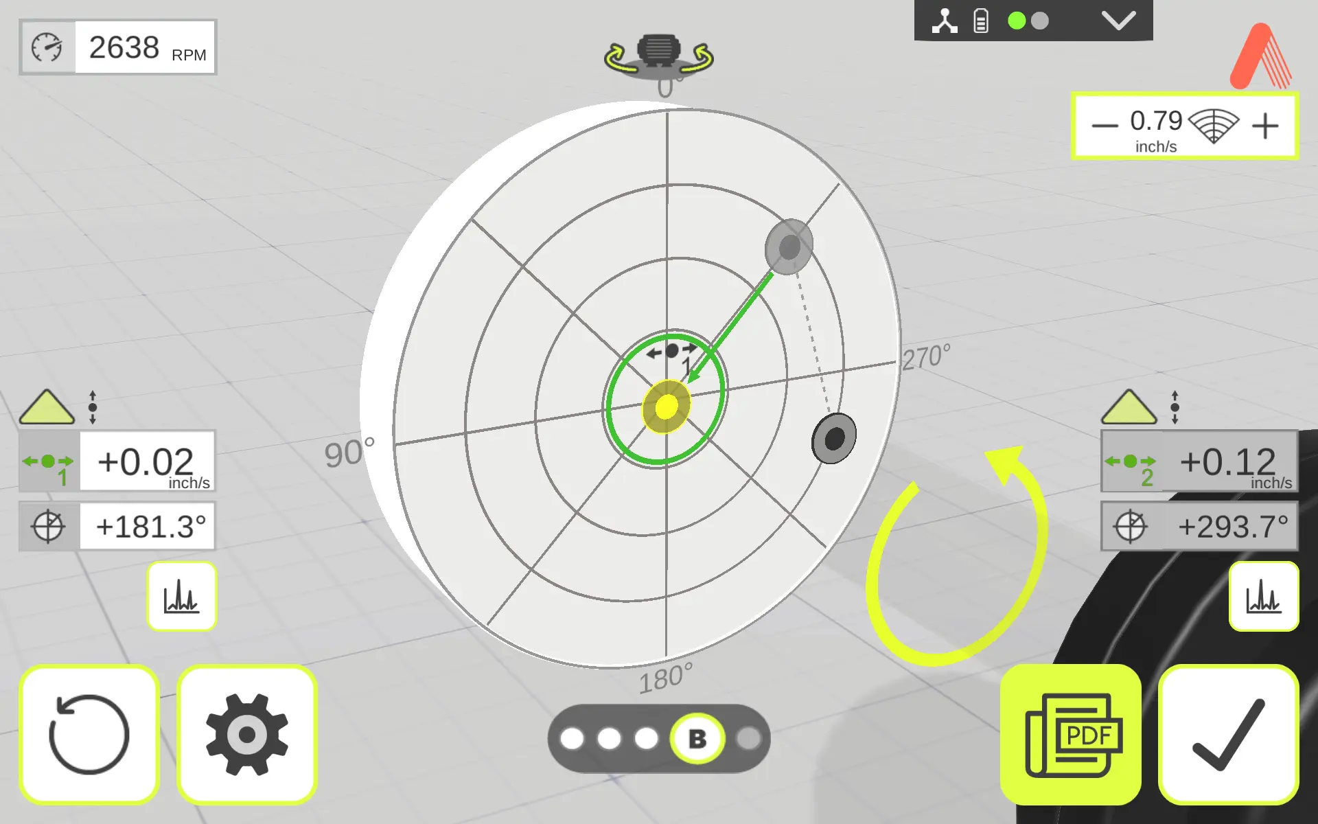 |
Balancing tolerances are only one part of achieving a reliable result. The following resources provide additional guidance on balancing procedures, trial weight selection, correction calculations, unbalance types, vibration standards, and other practical considerations for diagnosing and correcting rotational unbalance.
Additional Resources:
A Handy Guide to Balancing Machinery
Balancing How to #1 – Setting up for Balancing
Balancing How to #2 – Selecting a Proper Trial Weight
Balancing How to #3 – Where and How to Place and Affix a Trial Weight
Balancing How to #4 – Calculating a Trial Weight mathematically
Balancing How to #5 – How a Correction Weight and Location is Calculated
Balancing How to #6 – Balancing Tolerances
Static, Couple and Dynamic Unbalance
A Vector Approach to Single Plane Balancing